1.2 Identifying hazardous system behaviour
Practical guidance - cross-domain
Author: Stephan Baumgart (Volvo Autonomous Solutions) and Sasikumar Punnekkat (Mälardalen University, Sweden)
Autonomous vehicles are often used in fleets and integrated with other machines. Such connected and collaborating autonomous machines can be seen as a system-of-systems. It is not yet clear how to consider safety during the development of such system-of-systems (SoS). One potentially useful approach to analyse the safety for complex systems is the System Theoretic Process Analysis (STPA). However, STPA is essentially suitable to static monolithic systems and lacks the ability to deal with emergent and dysfunctional behaviours in the case of SoS. These behaviours if not identified could potentially lead to hazards and it is important to provide mechanisms for SoS developers/integrators to capture such critical situations.
System-Theoretic Process Analysis – STPA
To illustrate the application of STPA, we analyse the remote control case and follow the STPA process as described in literature [5]. At first we provide a short description of STPA.
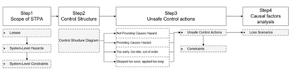
Figure 1 - General STPA Process as described in [5]
STPA consists of four steps as shown in Figure 1 which we describe in the following section.
STPA - Step 1: During the first step of STPA, the scope of the STPA is set and potential losses and hazards shall be identified. System-level hazards may be derived in brainstorming meetings with experts or by applying hazard identification methods like HAZOP or What-if Analysis. The list of possible system hazards may be extended during later stages when more product knowledge is available.
STPA - Step 2: In Step 2, the control structure of the system is derived. The control structure diagram is a graphical representation of the control actions to aid a structured analysis.
The control structure diagram contains the main control elements and control actions between the controllers and the controlled systems.
STPA - Step 3: The control structure diagram is used to apply a structured analysis of each control action and if a failure of the control action would lead to the already listed system-level hazards.
STPA uses four guide words for finding such unsafe control actions:
- Not providing causes hazard
- Providing causes hazard
- Too early, too late, out of order
- Stopped too soon, applied too long
This means that the following requirements are tested:
- A correct control action is provided
- A control action is provided at the correct time
- A control action is provided with correct duration
STPA - Step 4: In the last step of STPA, possible loss scenarios are identified for each unsafe control action. Reasoning why an unsafe control action would occur and how this could lead to a hazard shall be provided.
STPA - conclusion
STPA is useful for identifying and analysing control actions and their causal factors when unsafe control actions are identified. The process of STPA is foreseen to be iterative, i.e. it is possible that further system-level or subsystem-level hazards will be identified during later stages. It is furthermore proposed to add complexity to the control structure diagram during later stages of the development process. This will lead to additional efforts for identifying unsafe control actions in Step 3.
The question is, if STPA is able to deal with emergent and dysfunctional behaviours in the case of system-of-systems. These behaviours if not identified could potentially lead to hazards and it is important to provide mechanisms for SoS developers/integrators to capture such critical situations.
Industrial case study - electric site
The electric site research project [1] was used as a use case to illustrate the application of STPA. In this project a fleet of automated guided vehicles (AGVs) [2] called HX are used to transport material at a quarry site, which is a surface mine for gravel production in our case. The pre-crushed material is transported from a movable primary crusher to a stationary secondary crusher. Along with the fleet of autonomous HX, a human-operated wheel loader and a human-operated excavator are used for loading material onto the HX. In our earlier work we have described and analysed this complex SoS [3][4].
The fleet of active HX is controlled by the Fleet Control System, containing features like traffic management or setting missions for each active HX. Each HX is therefore highly dependent on the wireless network and correct commands. In order to be able to activate a HX in the morning, remove a HX for repair purposes or adding a HX to a running production, it is possible at any given instance to control a single HX using a remote control by a HX Remote Operator. The Site Operator is monitoring the quarry site from a control room, where the Site Server is located. In Figure 2 the involved systems and human operators are presented. When designing such a system an in-depth analysis of this scenario is necessary to identify potential hazards leading to critical accidents.

Figure 2 Use Case: Remote Control of HX
Application of STPA to the case study
In the following we apply STPA to the industrial case described above.
STPA Step 1 - Remote Control Case:
For our limited case we have identified two major losses that shall be avoided:
- Loss1: Humans injured or killed
- Situations, where humans are at risk to be injured or killed by the autonomous machines shall be avoided.
- Loss2: Damage of Equipment
- If machines are damaged because of accidents, this may result in a stop of production at the site, which shall be avoided.
Typical SoS hazards in our case can be:
- Hazard 1 (H-1): HX does not maintain safe distance to humans on site
- Hazard 2 (H-2): HX enters dangerous area/region
- Hazard 3 (H-3): Squeezing Hazard (e.g. people close to HX)
- Hazard 4 (H-4): Insufficient ability of machinery to be slowed down, stopped and immobilized
STPA Step 2 - Remote Control Case:
We simplified the control structure diagram for the purpose of this paper as shown in Figure 3.

Figure 3 - Control Structure Diagram: Remote Control HX 01
The HX Remote Operator sends a request to the Fleet Control server with the purpose to take over the control of a specific HX (HX 01). Fleet Control can decide either to accept (Grant Control) or to reject (Reject Control) the request. At the same time the Fleet Control is sharing information about the active HX with the site server shown by the message Info Status.
If the remote control request is accepted, Fleet Control is sending a task (Approve Checkout) to HX 01 to enable the HX to be controlled by the Remote Control. Once this is done, the HX Remote Operator can take control over the HX. The HX Remote Operator can also give back control of HX 01 to Fleet Control. Fleet Control will send a request (Take Control Back) to HX 01 that it will listen to controls send from Fleet Control.
STPA Step 3 - Remote Control Case:
Each message in the control structure diagram Figure 3 is analysed using the guide words.

Table 1 Unsafe Control Actions: Remote control case
We exemplify identifying unsafe control actions by analysing the messages “Request Control” and “Approve Checkout” in Table 1. Applying the first guide word “Not providing causes hazard” for “Request Control” helps finding the critical situations if the message is either not provided or lost, but this will not directly lead to a hazard. We identify the first unsafe control action (UCA 01) in the situation when the message “Request Control” is provided unintended. This may lead to a situation that a HX is checked out from Fleet Control without awareness of the HX Remote Operator. Humans are at risk, if the machine is moving into dangerous areas, where humans are working (H-2) or if humans are already close by, this may lead to squeezing hazards (H-3). If the signal is delayed (Too early, too late, out of order), this may lead in the worst case to frustration of the operator, but not to hazardous situations.
The message “Approve Checkout” is send from the Fleet Control to the HX to indicate, that the HX shall change mode to be controlled by a remote control. We identify, that providing “Approve Checkout” unintended, will lead to a situation where the HX is forced to switch over to be remote controlled. This can lead to critical situations where the HX is moving without a control instance connected to the machine.
Altogether, we have identified 15 UCAs for this simplified case during the first brainstorming.
STPA Step 4 - Remote Control Case:
In our case, "Approve Checkout'' might be provided unintended because of a fault in the Fleet Control software or due to a transmission error.
Conclusion from STPA case study
Where is STPA suitable?
STPA is a useful approach to analyse the safety of complex systems. While hazard analysis methods like PHA, FTA and FMEA focus on failures of system functions and their impact, STPA is analysing possible failures of control actions between the involved systems and sub-systems. This analysis leads to a broader list of possible critical scenarios that require further analysis to list all causal factors.
STPA is analysing the control actions and therefore mostly communication related hazards will be identified.
Which critical situations are not captured in STPA?
STPA analyses one single control action a time, which makes it impossible to find critical scenarios which involve for example a combination of control actions, cascading failures or state changes.
STPA is essentially suitable to static monolithic systems and lacks the ability to deal with emergent and dysfunctional behaviours in the case of SoS. These behaviours if not identified could potentially lead to hazards and it is important to provide mechanisms for SoS developers/integrators to capture such critical situations. It is among others important to check, if the involved systems in a SoS have a consistent perspective of the global state. The states of the involved systems are not considered in the control structure diagram of STPA. Design flaws and casual factors might be missed, if the interaction of state machines is not considered during analysis of the SoS.
Further details are available in [6].
A proposed extension to STPA
In [6] an approach is presented for enriching STPA to provide the ability to check whether the distributed constituent systems of a SoS have a consistent perspective of the global state. In Figure 4 we present our proposed enhancement of STPA. We exemplify three challenges regarding SoS, which require additional analysis efforts:
- Challenge 1: Inconsistent states in SoS.
- We need to be able to even consider the states of the involved systems in a SoS.
- Challenge 2: Communication deadlocks in SoS.
- When analysing single messages and control actions at a time, it might not be possible to identify if seemingly correct communication will lead to a deadlock.
- Challenge 3: Reachability of Safe States.
- When safe states are already considered, it needs to be checked and analysed if specific states can be reached or not. Because states are not considered in the standard STPA analysis, this need to be added.

As shown in Figure 4 we foresee the need for additional formalisms, methods and tools to support an analysis for SoS. Such a method is for example Petri nets, which we applied to identify inconsistencies in a SoS. An interested reader may refer [6] for further details on usage of Petri nets in an SoS context.
References
- [1] Volvo Construction Equipment, “Electric Site Project.” [Online]. Available: https://www.volvoce.com/global/en/news- and- events/news-and- pressreleases/2018/carbon- emissions- reduced- by- 98- at- volvo-construction- equipment-andskanskas-electric- site/
- [2] D. Weyns, T. Holvoet, and K. Schelfthout, “Decentralized control of automatic guided vehicles: applying multi-agent systems in practice,” Companion to the 23rd, 2008. [Online]. Available: http: //dl.acm.org/citation.cfm?id=1449819
- [3] S. Baumgart, J. Froberg, and S. Punnekkat, “Analyzing hazards in system-of-systems: Described in a quarry site automation context,” in 2017 Annual IEEE International Systems Conference (SysCon). IEEE, 4 2017, pp. 1–8. [Online]. Available: http://ieeexplore.ieee.org/document/7934783/
- [4] S. Baumgart, J. Froberg, and S. Punnekkat, “Can STPA be used for a System-of-Systems? Experiences from an Automated Quarry Site,” in 2018 IEEE International Systems Engineering Symposium (ISSE), no. 4. IEEE, 10 2018, pp. 1–8. [Online]. Available: http://www.es.mdh.se/publications/5246-https: //ieeexplore.ieee.org/document/8544433/
- [5] N. G. Leveson and J. P. Thomas, STPA Handbook, 2018.
- [6] S. Baumgart, J. Fröberg and S. Punnekkat, "A State-based Extension to STPA for Safety-Critical System-of-Systems," 4th International Conference on System Reliability and Safety (ICSRS), Rome, Italy, 2019, pp. 246-254, doi: 10.1109/ICSRS48664.2019.8987632
Contact us
Assuring Autonomy International Programme
assuring-autonomy@york.ac.uk
+44 (0)1904 325345
Institute for Safe Autonomy, University of York, Deramore Lane, York YO10 5GH
Related links
Download this guidance as a PDF:
Contact us
Assuring Autonomy International Programme
assuring-autonomy@york.ac.uk
+44 (0)1904 325345
Institute for Safe Autonomy, University of York, Deramore Lane, York YO10 5GH
Related links
Download this guidance as a PDF: