2.6.1 – Monitoring RAS operation
Practical guidance - cobots
Authors: Peng Wang, Shenglin Wang, James Law, Lyudmila Mihaylova (CSI:Cobot demonstrator project)
This guidance provides a generic framework for safe sensing and decision-making by ensuring the safety of a collaborative robot and an operator using widely available optical camera systems.
A collaborative robot (cobot) is a robot that is capable of being used in a collaborative operation alongside humans in a shared workspace. Cobots are “designed with a variety of technical features that ensure they do not cause harm when a worker comes into direct contact, either deliberately or by accident” [2]. This guidance outlines an approach to safety sensing using convolutional neural networks (CNNs) to determine the separation of robots and operators in shared spaces.
This guidance refers to the defined workspace as a working cell, or simply ‘cell’ hereafter, in which humans are working in close proximity to robots. Typically, human operators are separated from robotic equipment by physical safety fences and barriers, or by safety sensors such as light gates, proximity scanners, optical safety cameras, etc., which prohibit complex human-robot collaboration, impose fixed and space-demanding infrastructure, reduce operational flexibility, and can be costly [1, 3]. In response to these challenges, this guidance proposes a more flexible approach to safety sensing and decision-making by applying sophisticated learning approaches to visual feeds from widely available optical camera systems.
The safe sensing and decision making (S2DeMa) framework aims at identifying behaviours of the robot and the operator that could lead to harmful consequences to both parties. The framework is composed of a camera system for perception and a CNN module for object detection and decision making. The identification of hazardous behaviours and upon which decisions are made to either slow down the robot or warn the operator of potential risks hold the promise of 1) ensuring safe collaborative operation; 2) increasing flexibility in collaborative operation (such as responsive collaboration as defined in [2]). This will also serve as a prerequisite to enable robots to move and work safely alongside humans in open space, for meeting the modern demands of mass-customisation, higher product variability and quality expectations, and faster product cycles [4].
Summary of S2DeMa framework
The main steps of S2DeMa are:
- Setting up the visual monitoring system
- Implementation of mask R-CNN [5] for object detection and classification
- Data preparation
- Model selection, training, and testing
- Safe decision making with confidence quantification
- Determine safety criteria of collaborative operation between the operator and the robot
Implementation of the approach
The application of the S2DeMa framework requires:
- a collaborative workspace containing humans and robots
- a vision system covering areas of potential contact/interaction
- a criterion for safety decision-making, based on the detected proximity of entities
The minimum setup should include a human operator, a robot, and a visual monitoring system containing at least one camera. The system monitors a collaborative workspace, using images gathered from the camera to identify and track humans and robots in the space. Bounding boxes applied to tracked entities are used to identify potential collisions when objects overlap or come in close proximity in the image space. The bounding boxes are also transformed into physical world coordinates for other practical applications. A separate ruleset for decision-making is required to determine how to interpret proximity information and bounding-box overlaps. Below we describe the results of applying a minimally configured S2DeMa framework. The main steps of S2DeMa are:
1. Setting up the visual monitoring system
The visual system plays a key role in implementing the S2DeMa framework. It collects data for the object detection module, which is a mask R-CNN in this guidance. The S2DeMa framework also relies on the visual system to transform detection results from the image space to the physical world, to enable higher level decision making.
Figure 1 shows a typical visual monitoring system, where the camera Oc is mounted above the robot, looking down over the workspace. Measuring the relative position of the camera with respect to the robot base coordinate system OB manually is usually inaccurate. Therefore, one needs to calibrate the visual system to ensure correct sensing and decision-making. To be specific, two types of calibration need to be carried out:
- Obtain the intrinsic and extrinsic camera matrices following the method proposed [6]
- Obtain the relative position of the camera in OB by carrying out the eye to hand (Eye2Hand) calibration as shown in Figure 1.
Note that OT and OE denote the coordinate systems of the robot effector and an attached checkerboard as shown in Figure 1 used for Eye2Hand calibration.
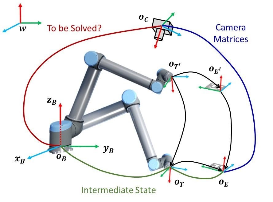
Figure 1 - Eye2Hand camera calibration
2. Implementation of mask R-CNN for object detection and classification
The implementation of mask R-CNN for the detection and classification of the operator and the robot involves two steps as follows:
2.1 Data preparation
a. Real data
Camera data is collected on the operator, robot, and environment, carrying out typical actions (but under safe conditions). Image size and resolution should be adjusted depending on the capacity of the hardware and the process of interest. The recorded data are stored locally for model training.
In our example, the camera records images of size 1920 x 1080 at 30 fps. However, there is no hard requirement of the image size. The input images can be re-scaled to meet the requirements of the mask R-CNN. Typical image size can be found in [7] as 1024 x 1024. The robot base must be fixed firmly to avoid vibration of the robot arm - such vibrations could lead to blurred images that cause performance degradation of the mask R-CNN model.
Before training the mask R-CNN model, the raw data needs to be annotated. This guidance utilises LabelMe [8] for robot contour and bounding box annotation. Up to 1000 robot images are annotated for mask R-CNN training. Human data from COCO [9] are used for operator detection. Up to 2000 human images are extracted. In total there are 3000 real images prepared. This dataset will be augmented later to improve detection and classification performance. There is no general standard for the number of real images. In this case, 32,028 images with 3000 real images and 29,028 simulated images are used for model training. In general, the number of images is positively correlated with the performance of the trained mask R-CNN model.
b. Virtual augmented data
Data annotation is notoriously labour intensive. Unfortunately, it is critical in improving the performance of the mask R-CNN model. This problem is mitigated by taking advantage of computer-based simulators to generate robot data with contour information, which can be further used to produce bounding boxes. Figure 2 compares a simulated robot and a real robot. The advantages of using such computer-based simulators also include adjusting light condition, randomise background for data augmentation, etc. The mask R-CNN model can henceforth be trained by simulated data and next generalised to process real data. Domain Randomisation (DR) [10] and Domain Adaptation (DA) [11] can be incorporated to bridge the gap between the real and simulated data, to improve model performance during generalisation.
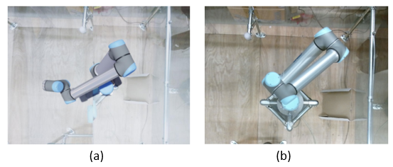
Figure 2 - Examples of a simulated robot and a real robot
2.2 Model selection, training, and testing
Model selection is another factor that affects the performance of the S2DeMa framework besides datasets. In particular, the backbone CNNs used for feature extraction have prominent impacts on detection accuracy and efficiency. There exists a series of backbone CNNs, with strength in either accuracy or efficiency, or a compromise of the two. One can select the backbone CNN according to requirements of the task. The model should in minimum output both classification and detection results, as shown in Figure 3. The classification tells if an object is the operator or the robot, while the detection yields a bounding box that encloses the object.
When the backbone CNN is determined, model training and testing can be carried out subsequently. In general, one takes 70% of the images for training and the remaining 30% for testing. The metrics for evaluating the training and testing accuracy are twofold:
- for detection, the Average Precision (AP), AP50 (AP at IoU = 0.50, IoU: Intersection over Union), and AP75 (AP at IoU = 0.75) are used
- for classification, the Accuracy = (TP+TN)/(TP+FP+FN+TN), Precision = (TP)/(TP+FP), and Recall = (TP)/(TP+FN) are mostly used, where TP stands for True Positive, FP is False Positive, TN represents True Negative, and FN is False Negative [12].
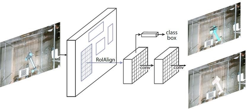
Figure 3 - The mask R-CNN framework for object detection and classification [5]
3. Safe decision making with confidence quantification
Ensuring safe collaborative operation, especially in the presence of human operators, requires not only classification and detection of the operator and the robot, but also a measure of confidence in that detection. The confidence quantification process is, however, inherently iterative. It should be refined in parallel with the development of the control mechanism and other safety and security measures.
This guidance considers two types of confidence on the results:
- classification confidence
- confidence while transferring bounding box coordinates from image space to the physical world.
The first type of confidence indicates how confident the model is on the image classification results. For instance, when the model classifies an object to be an operator with 98% confidence, it means that the model is confident in the classification result. To ensure safety, this guidance sets a confidence threshold, for instance 80% for classification. Any classification results with confidence below the threshold will be discarded (it is possible that the mask R-CNN does not detect the object of interests in one image - this can be mitigated when streaming data are processed, which is the case in this guidance). The second type of confidence counts for the inaccuracy of camera calibration. The calibration can be repeated independently multiple times (five in our case), each time with a set of camera matrices. The bounding box coordinates in the image space can then be transformed into the physical world with each set of camera matrices and a statistical variance σ can be obtained. It can be taken as a measure to expand the physical area corresponding to a bounding box to further ensure safety.
4. Determine safety criteria of collaborative operation between the operator and the robot
Mask R-CNN is able to detect objects of interest (the operator and the robot) and use bounding boxes to indicate the areas where the objects are most likely to locate. Mounting the camera on the roof of cell enables us to detect the operator and the robot in a horizontal two-dimensional space. This substantially provides a way of defining the criteria for safe collaborative operation. Suppose one has obtained the bounding boxes of the operator and the robot, and overlap (indicated by red rectangles in Figure 4) between the two bounding boxes that is denoted as OVERLAP. The coordinates of these bounding boxes are transformed from the image space to the physical world and the area of the bounding boxes and the OVERLAP can therefore be calculated. The safety criteria are then defined as:
- Safe: If the area of OVERLAP is below the safe threshold S, as shown in Figure 4 (a);
- Potential: If the area of OVERLAP is between the safe threshold S and the dangerous threshold D, as shown in Figure 4 (b);
- Dangerous: If the area of OVERLAP is over the dangerous threshold D, as shown in Figure 4 (c).
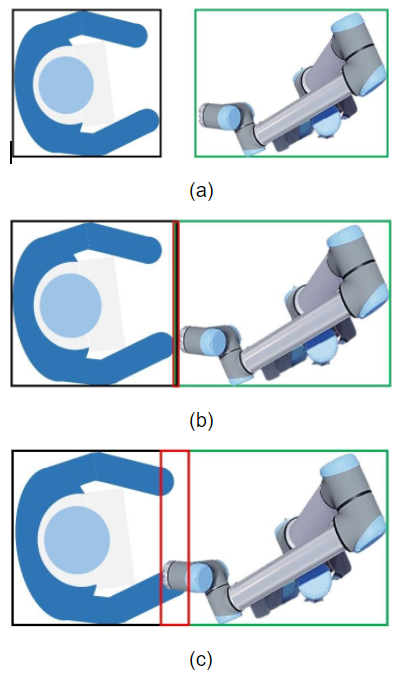
Figure 4 - Safety criteria: (a) Safe; (b) Potential; (c) Dangerous. The red rectangles indicate the overlapping areas.
Example of application of guidance
The framework is implemented and tested in a single operator, single robot collaborative cell, and a camera is installed overhead as shown in Figure 5. This is a minimum configuration of the framework, which can be generalised to detect multiple human operators and robots within the Field Of View (FOV) of the camera. The state-of-the-art deep-learning-based object detection and segmentation method - mask R-CNN [5] is implemented to detect the robot and the operator, along with confidence quantification of the detection results.
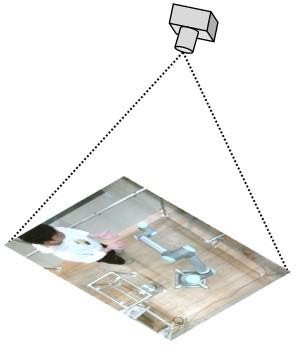
Figure 5 - The camera and top view of the cell
In this example, a Kinect V2 is used for data collection, the backbone of the mask R-CNN model is ResNet101-RPN [13]. The number of images (real plus simulated data, with a simulated-to-real ratio of 1:1; real data includes that extracted from COCO for human detection) in the training dataset is 24021, while the testing dataset contains 8007 images with the same simulated-to-real data ratio. Figure 4 shows the object detection and classification results with classification confidence embedded in each subfigure. In this example we not only show the detection results of the operator and the robot, but also demonstrate the possibility of detection and classification of each component of the robot for finer sensing and decision making. In this example, the robot is decomposed into four components, i.e. the base, the shoulder, the elbow, and the wrist. We can see that the S2DeMa framework has successfully detected the operator, the robot, and the robot components with high confidence.
The safe threshold S and the dangerous threshold D are set to 0 and 10, respectively. This means that if the bounding boxes of the robot and the operator overlap each other, we consider it as potential risk. When the overlap exceeds 10 pixels, we take it as dangerous. This happens when then bounding box of the operator starts overlapping the bounding box of the robot. It is rather conservative, but helps to ensure safety of both parties.
In this example, given the upper left vertex of a bounding box (Ix,Iy), it is transformed to the physical world via [14]
![]() (1)
(1)
where the left-hand vector is the homogenous physical world coordinates, R is the rotation matrix and T is the translation matrix, Zc is the coordinate of OC in OB and K is the intrinsic matrix. Note K-1 is used to ensure the coordinates are with respect to the robot base coordinate system OB rather than the camera coordinate system OC to generalise the framework. We only consider the movements of the robot and the operator in the xoy plane in this example. The variance σ calculated from camera calibration is 5 cm. Hence, when the confidence level is considered, the upper left vertex will be changed following the rules:
68% confidence upper left vertex: ![]()
95% confidence upper left vertex: ![]()
99.7% confidence upper left vertex: ![]()
For instance, after transforming the upper left vertices of the bounding boxes in Figure 6 (a) via Eq. (1), one can get the following physical world coordinates with respect to OB:
Table 1: World coordinates corresponding to the upper left vertices of the bounding boxes Figure 6
| Object | Operator | Base | Shoulder | Elbow | Wrist | Robot |
|---|---|---|---|---|---|---|
| (x, y) (cm) | (-194.6, 39.0) | (-5.6, 1.1) | (-48.4, -32.1) | (-102.1, -17.8) | (-115.2, -32.3) | (-113.7, 34.4) |
Given σ as 5 cm, one can therefore get the coordinates of 68%, 95%, and 99.7% confidence as follows:
1) 68% confidence:
Table 2: World coordinates with 68% confidence corresponding to Table 1.
| Object | Operator | Base | Shoulder | Elbow | Wrist | Robot |
|---|---|---|---|---|---|---|
| (x, y) (cm) | (-199.6, 34.0) | (-10.6, -4.1) | (-53.4, -37.1) | (-107.1, -22.8) | (-120.2, -37.3) | (-118.7, -39.4) |
2) 95% confidence:
Table 3: World coordinates with 95% confidence corresponding to Table 1.
| Object | Operator | Base | Shoulder | Elbow | Wrist | Robot |
|---|---|---|---|---|---|---|
| (x, y) (cm) | (-204.6, 29.0) | (-15.6, -9.1) | (-58.4, -42.1) | (-112.1, -27.8) | (-125.2, -42.3) | (-123.7, -44.4) |
3) 99.7% confidence:
Table 4: World coordinates with 99.7% confidence corresponding to Table 1.
| Object | Operator | Base | Shoulder | Elbow | Wrist | Robot |
|---|---|---|---|---|---|---|
| (x, y) (cm) | (-209.6, 24.0) | (-20.6, -14.1) | (-63.4, -47.1) | (-117.1, -32.8) | (-130.2, -47.3) | (-128.7, -49.4) |
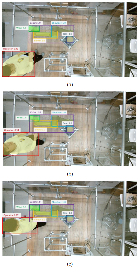
Figure 6 - The detection and classification results: (a) Safe; (b) Potential; (c) Dangerous
The original bounding boxes and the bounding boxes that corresponding to the 68%, 95%, and 99.7% confidence are shown in Figure 7. For clarity, we only shown the bounding boxes of the operator and the robot. We see that by expanding the bounding boxes, the framework becomes conservative in determining if the behaviours of the operator of the robot are safe. However, it helps ensuring safety. Figure 7 (a), Figure 7 (b), and Figure 7 (c) correspond to Figure 6 (a), Figure 6 (b), and Figure 6 (c). For clarity, the detection masks are not shown in Figure 7.
Summary of findings
The S2DeMa framework utilises neural-network-based learning to visually classify and detect robots and operators in a collaborative workspace, for the purpose of making safety decisions based on the separation of entities. The framework is also designed to be capable of potential extension and generalisation. A three-level safety criteria is proposed for decision making. We summarise the major findings along with the development of the S2DeMa framework as follows:
- Camera calibration is crucial for the S2DeMa framework due to the demand of transforming bounding box coordinates in the image space to the physical world. A small error in camera calibration could lead to errors in bounding box calculations and possible collisions. This can be countered by repeating the calibration process multiple times and taking an average. The statistical variance is used to expand the physical area that corresponds to a bounding box to further ensure safety.
- Real data preparation is labour intensive, which can be mitigated by employing a computer-based simulator to generate robot data that are of fairly high fidelity. These simulated data can be used to train the object detection model. Adaptation and domain randomisation techniques can be incorporated to improve the model performance when it is generalised to process real data.
- The efficiency of the S2DeMa is mainly determined by the backbone CNN used for object detection and classification. It also affects the detection and classification accuracy. The backbone CNN is designed to be an independent module that can be adjusted case by case.
- The classification confidence and the inaccuracy caused by camera calibration are counted for confidence quantification in this guidance. However, it is worth mentioning that the confidence quantification process is inherently iterative. It should be refined in progress with the development of the control mechanism and other safety and security measures.
- Whilst this report outlines how neural networks can be used to detect and classify entities for use in safety decision making, the approach is not yet certified for industrial use, and should not be relied upon as the sole safety system for a collaborative robot.
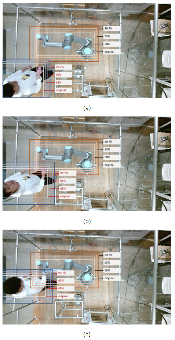
Figure 7 - Bounding boxes with confidence: (a) Safe; (b) Potential; (c) Dangerous
References
- [1] “ISO - ISO/TS 15066:2016 - Robots and robotic devices — Collaborative robots.” [Online]. Available: https://www.iso.org/standard/62996.html. [Accessed: 08-Jan-2021].
- [2] “Demystifying Collaborative Industrial Robots,” International Federation of Robotics, 2018.
- [3] “ISO - ISO 10218-1:2011 - Robots and robotic devices — Safety requirements for industrial robots — Part 1: Robots.” [Online]. Available: https://www.iso.org/standard/51330.html. [Accessed: 13-Jan-2021].
- [4] “Veo Robotics.” [Online]. Available: https://www.veobot.com/. [Accessed: 13-Jan-2021].
- [5] K. He, G. Gkioxari, P. Dollár, and R. Girshick, “Mask R-CNN,” IEEE Trans. Pattern Anal. Mach. Intell., vol. 42, no. 2, pp. 386–397, Feb. 2020.
- [6] Z. Zhang, “A flexible new technique for camera calibration,” IEEE Trans. Pattern Anal. Mach. Intell., vol. 22, no. 11, pp. 1330–1334, Nov. 2000.
- [7] “GitHub - matterport/Mask_RCNN: Mask R-CNN for object detection and instance segmentation on Keras and TensorFlow.” [Online]. Available: https://github.com/matterport/Mask_RCNN. [Accessed: 13-Jan-2021].
- [8] “LabelMe. The Open annotation tool.” [Online]. Available: http://labelme.csail.mit.edu/Release3.0/. [Accessed: 08-Jan-2021].
- [9] “COCO - Common Objects in Context.” [Online]. Available: https://cocodataset.org/#home. [Accessed: 08-Jan-2021].
- [10] J. Tobin, R. Fong, A. Ray, J. Schneider, W. Zaremba, and P. Abbeel, “Domain Randomization for Transferring Deep Neural Networks from Simulation to the Real World,” in Proceedings of IEEE International Conference on Intelligent Robots and Systems, 2017, vol. 2017-Septe, pp. 23–30.
- [11] Y. Ganin et al., “Domain-Adversarial Training of Neural Networks,” Adv. Comput. Vis. Pattern Recognit., vol. 17, no. 9783319583464, pp. 189–209, May 2015.
- [12] “Accuracy, Recall, Precision, F-Score & Specificity, which to optimize on? | by Salma Ghoneim | Towards Data Science.” [Online]. Available: https://towardsdatascience.com/accuracy-recall-precision-f-score-specificity-which-to-optimize-on-867d3f11124. [Accessed: 14-Jan-2021].
- [13] FAIR, “CNN backbones.” [Online]. Available: https://github.com/facebookresearch/detectron2/blob/master/MODEL_ZOO.md.
- [14] P. Wang, Y. Lin, R. Muroiwa, S. Pike, and L. Mihaylova, “A weighted variance approach for uncertainty quantification in high quality steel rolling,” in Proceedings of 2020 23rd International Conference on Information Fusion, FUSION 2020, 2020.
Abbreviations
- CNNs – Convolutional Neural Networks
- R-CNN – Region-based CNN
- LiDAR – Light Detection And Ranging
- S2DeMa – Safe Sensing and Decision Making
- Eye2Hand – Eye to Hand
- FOV – Field Of View
- DR – Domain Randomisation
- DA – Domain Adaptation
- AP – Average Precision
- IoU – Intersection over Union
- AP50 – AP at IoU = 0.50
- AP75 – AP at IoU = 0.75
- TP – True Positive
- FP – False Positive
- TN – True Negative
- FN – False Negative
Terminology [1]
- Robot – Robot arm & robot control (does not include end-effector or part)
- Robot system – Robot, end-effector and workpiece +
- Maximum space – Space within which a robot system can move
- Restricted space – Portion of the maximum space restricted by limiting devices that establish limits which will not be exceeded
- Operating space – Portion of the restricted space that is actually used while performing all motions commanded by the task program
- Safeguarded space – Space defined by the perimeter safeguarding
- Operator(s) – All personnel, not simply production operators, including maintenance, troubleshooting, setup, cleaning and production.
Contact us
Assuring Autonomy International Programme
assuring-autonomy@york.ac.uk
+44 (0)1904 325345
Institute for Safe Autonomy, University of York, Deramore Lane, York YO10 5GH
Contact us
Assuring Autonomy International Programme
assuring-autonomy@york.ac.uk
+44 (0)1904 325345
Institute for Safe Autonomy, University of York, Deramore Lane, York YO10 5GH